 Email:sales04@bdhuazheng.com
 Cellphone/ wechat/Whatsapp /Skype: +86 18330222302


Email:sales04@bdhuazheng.com
Cellphone/ wechat/Whatsapp /Skype: +86 18330222302

Its main business is the production, manufacture and sales of electrical equipment and testing instruments.
Circuit breakers undergo characteristic tests before they are shipped out of the factory, before they are put into operation in substations, and during regular maintenance. What exactly is this "characteristic test" verifying? Simply put, it verifies two things: Can the circuit breaker reliably trip under a specified short-circuit current? And is the timing of the trip correct?
Test principle
Overcurrent protection for circuit breakers falls into two categories: one is thermal-magnetic type (commonly used in low-voltage circuit breakers), relying on the combined action of bimetallic strips and electromagnets; the other is electronic type (intelligent circuit breakers), relying on the judgment of electronic trip units. Regardless of the type, the testing method is the same - apply a current exceeding the setting value of the circuit breaker, record the action time, and compare it with the manufacturer's factory curve.
The current here is not just a few amperes or tens of amperes, but often three, five, or even ten times the rated value. That's why ordinary power supplies simply can't handle this task and a specialized high-current generator is necessary.
The necessity of three-camera models
The three poles of a three-phase circuit breaker usually require simultaneous current flow. Testing each pole separately and then superimposing the results can easily overlook issues related to three-phase linkage. By using a three-phase high-current generator with one wiring connection and applying three-phase currents simultaneously, the test results can truly reflect the protective behavior of the circuit breaker under actual operating conditions.
In addition, the three-phase model can also perform a "phase loss" test - disconnecting one phase current to verify whether the circuit breaker can trip correctly when there is single-phase overcurrent. This is something that single-phase current boosters cannot achieve.
The details of wiring determine success or failure
Many people encounter abnormal current display during circuit breaker tests, which is often not due to equipment malfunction but rather a wiring issue: the current loop has not formed a closed circuit. The output terminal of the current booster must pass through the main circuit of the circuit breaker under test to form a loop; otherwise, the device will not output current. This is a basic circuit requirement for current transformer-type devices.
Insufficient cross-sectional area of the current conductor is also a common issue during testing. It is recommended to use conductors with a current capacity of 10A/mm², to avoid overheating of the conductor during testing, which could affect the readings.
frequency issue
The domestic power grid operates at a frequency of 50Hz. The frequency of the AC current output by the high-current generator should align with the design frequency of the device under test, ensuring accurate thermal effects in the bimetallic strip of a thermal-magnetic circuit breaker. A legitimate current booster should produce a standard mains frequency sine wave, which should be confirmed during purchase.
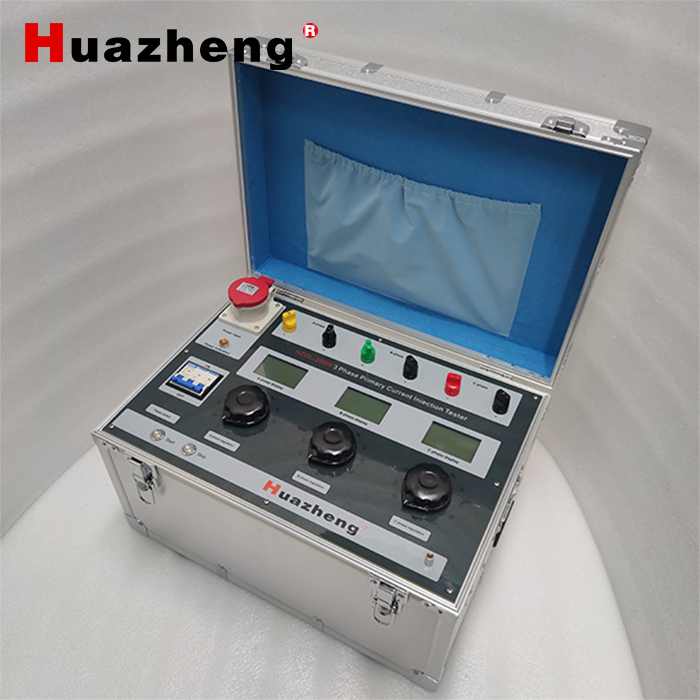
HZDL-200III 3 Phase Primary Current Injection Tester


Contact : Summer Xu

Position: Sales Manager

Email: sales04@bdhuazheng.com

Cellphone/ wechat/Whatsapp /Skype : +86 18330222302

Address: Unit 3, Building 9, No. 3099 Xiangyang North Street, Gaokai District, Baoding,Hebei,China,Zip: 071000

 sales04@bdhuazheng.com
 +86 18330222302
 +86 18330222302
 +86 18330222302
 +86 18330222302
