 Email:sales04@bdhuazheng.com
 Cellphone/ wechat/Whatsapp /Skype: +86 18330222302


Email:sales04@bdhuazheng.com
Cellphone/ wechat/Whatsapp /Skype: +86 18330222302

Its main business is the production, manufacture and sales of electrical equipment and testing instruments.
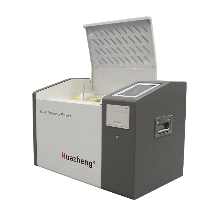
The core working principle of the insulation oil withstand voltage tester is to simulate the electric field environment during the actual operation of power equipment. By applying a steadily increasing AC high voltage to the insulation oil sample until it undergoes breakdown discharge, the insulation performance is quantified based on the measured breakdown voltage value, providing a key basis for the safe operation of the equipment.
Core working mechanism and physical logic
The insulation performance of insulating oil is essentially its ability to obstruct the passage of current, and breakdown voltage is the core indicator of this performance. Pure insulating oil molecules have a stable structure and can withstand high electric field strengths; But when water, impurities, sludge, or polar substances are mixed into the oil due to aging, these substances become "weak points" in the electric field, leading to a significant decrease in the withstand voltage of the oil sample.
The core logic of the tester is to apply a standardized electric field to expose the insulation short board of the oil sample under controllable conditions: under the action of the electric field, impurities in the oil will form a "leader" of the conductive path. When the voltage rises enough to break through the insulation limit of the oil sample, an instantaneous discharge phenomenon will occur, and the voltage at this time is the breakdown voltage, which directly reflects the current insulation level of the oil sample.
Detailed workflow
Oil sample pretreatment and placement: First, according to standards such as GB/T 507 and IEC 60156, heat the insulation oil sample to the specified temperature (usually 20-25 ℃), remove bubbles, and then inject it into a dedicated standard oil cup. The parallel electrodes inside the oil cup must strictly maintain the specified spacing (usually 2.5mm, adjustable in some scenarios), and the electrode material should be selected from high voltage and corrosion-resistant brass or stainless steel to ensure uniform distribution of the electric field.
High voltage generation and smooth boosting: The instrument converts the mains power (220V/380V) into adjustable AC high voltage through its built-in high voltage transformer, rectification and filtering circuit, and voltage regulation module. The boosting process adopts a uniform design, and the boosting rate is set according to the standard (such as 2kV/s) to avoid voltage fluctuations that may cause distortion in breakdown voltage measurement. At the same time, the stability of the output voltage is ensured through a voltage regulator circuit.
Breakdown detection and signal capture: As the voltage gradually increases, the electric field strength between the electrodes of the oil sample continues to increase. When the voltage reaches the critical tolerance value of the oil sample, an instantaneous conductive channel will form in the oil, resulting in breakdown discharge - manifested as a sudden increase in current and a momentary drop in voltage. The high-precision current sensor and voltage detection circuit built into the instrument will instantly capture this signal, with a response time typically in milliseconds.
High voltage cut-off and data recording: After capturing the breakdown signal, the instrument immediately triggers the protection mechanism to quickly cut off the high voltage output through thyristors or relays, preventing continuous discharge from damaging the electrodes or oil samples. At the same time, the data acquisition module will record the peak voltage at the moment of breakdown, which is the breakdown voltage of the oil sample tested.
Multi group testing and result processing: To avoid the randomness of a single test, the instrument supports multiple parallel tests (usually 3-6 times) according to standard requirements. After the test is completed, the system will automatically remove abnormal data (such as low values caused by bubbles), calculate statistical results such as average, maximum, and minimum values, and display or print them directly.
Key technical support and design points
Standardized design of electric field: The shape of the electrode (usually a circular flat plate), surface smoothness, and spacing strictly follow international/domestic standards to avoid electric field distortion, ensure that the testing environment is consistent with the actual working conditions inside the power equipment, and ensure the comparability and accuracy of the testing results.
High voltage protection mechanism: In addition to rapid power-off after breakdown, the instrument also has multiple safety designs such as overcurrent protection, overvoltage protection, and leakage protection. When abnormal current, excessive voltage, or equipment leakage occurs during the testing process, the high-voltage circuit will be immediately cut off and an alarm will be triggered to ensure the safety of operators and equipment.
Anti interference design: By using techniques such as shielding grounding and filtering circuits, the impact of power grid interference and electromagnetic radiation on test signals is suppressed, avoiding false triggering or data deviation caused by clutter, especially suitable for on-site detection in complex industrial environments.
Temperature and environmental compensation: Some high-precision instruments have temperature compensation function, which can automatically correct the breakdown voltage value based on the oil sample test temperature, eliminate the influence of temperature on the insulation oil performance, and make the detection results more in line with the insulation state under the actual operating temperature of the equipment.


Contact : Summer Xu

Position: Sales Manager

Email: sales04@bdhuazheng.com

Cellphone/ wechat/Whatsapp /Skype : +86 18330222302

Address: Unit 3, Building 9, No. 3099 Xiangyang North Street, Gaokai District, Baoding,Hebei,China,Zip: 071000

 sales04@bdhuazheng.com
 +86 18330222302
 +86 18330222302
 +86 18330222302
 +86 18330222302
