 Email:sales04@bdhuazheng.com
 Cellphone/ wechat/Whatsapp /Skype: +86 18330222302


Email:sales04@bdhuazheng.com
Cellphone/ wechat/Whatsapp /Skype: +86 18330222302

Its main business is the production, manufacture and sales of electrical equipment and testing instruments.
1、 Distance measurement principle (rough measurement of fault distance)
Pulse reflection method
Principle: Inject low or high voltage pulse signals into the cable, and when the pulse encounters a fault point (impedance jump point, such as short circuit, open circuit, or high resistance fault), a reflected wave will be generated. The instrument records the time difference (Δ T) between the emitted pulse and the reflected pulse, combined with the propagation speed (V) of the pulse in the cable, to calculate the fault distance: Lx=V ·Δ T/2.
Category:
Low voltage pulse method: suitable for low resistance faults (resistance<1k Ω), open or short circuit faults, directly obtaining reflected waveforms.
High voltage flashover method: For high resistance faults (resistance>100k Ω), an instantaneous short circuit is formed by high-voltage breakdown of the fault point, and then the reflected waveform is collected (such as direct flashover method, impulse flashover method).
Secondary/tertiary pulse method
Improvement point: Solve the problem of complex and difficult analysis of traditional high-voltage flashover waveforms.
Secondary pulse method: After the high voltage penetrates the fault point, a low voltage pulse is immediately injected. The fault point exhibits a reflection waveform similar to a low resistance fault due to arc short circuit (when superimposed with the full-length waveform, the discrete point is the fault point).
Triple pulse method: Adding medium voltage stable arc pulse on the basis of the secondary pulse, extending the arc time, further improving waveform stability and interpretation accuracy.
Bridge method
Principle: Based on the Wheatstone bridge balance principle, the fault distance is calculated by comparing the resistance ratio between the faulty phase and the intact phase (the total length of the cable needs to be known).
Applicable scenarios: Low resistance leakage faults (<600M Ω), but ineffective for high resistance faults and flashover faults.
2、 Fixed point principle (precise positioning of fault points)
Acoustic magnetic synchronization method
Principle: High voltage impact generates discharge at the fault point, synchronously receiving electromagnetic wave signals (fast propagation speed) and sound wave signals (slow propagation speed), and determining the location of the fault point through time difference and signal strength.
Step voltage method
Principle: Applying direct current or pulse voltage to a faulty cable will create a potential gradient on the surrounding ground when the fault point is grounded. Measure the potential difference along the path, and the potential jump point (step voltage zero point) is the fault point, which is suitable for low resistance grounding faults of damaged outer sheaths or buried cables.
Audio induction method
Principle: Inject audio current into the cable, causing magnetic field anomalies at the fault point due to impedance changes. Using a receiver to detect changes in magnetic field strength, the weakest point of the signal is the fault point, suitable for low impedance faults or path searching.
3、 System workflow
Fault nature determination
First, measure the insulation resistance of the cable to distinguish between low resistance (<10k Ω), high resistance (>100k Ω), or flashover faults.
Distance measurement operation
Low resistance/open circuit fault → Low voltage pulse method.
High resistance fault → High voltage flashover method or secondary/tertiary pulse method.
Path positioning (optional)
Use an audio pathfinder or pulse magnetic field method to determine the direction of cable burial.
Accurate positioning
Combining acoustic magnetic synchronization method (mainstream) or step voltage method, accurately locate near the rough measurement position.
4、 Key technical support
High speed sampling and digital processing: Modern instruments capture transient waveforms through high-speed A/D converters, filter, superimpose, and compare them with microprocessors, automatically calculate distances, and display waveforms (such as real-time display of reflected waves on LCD screens).
Safety protection mechanism: Electrical isolation technology is used during high-voltage impact to ensure that the instrument does not crash under the impact voltage (such as voltage divider resistor and filter design).
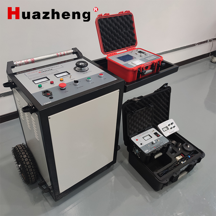
Huazheng Electric HZ-501B Integrated Cable Fault Locator


Contact : Summer Xu

Position: Sales Manager

Email: sales04@bdhuazheng.com

Cellphone/ wechat/Whatsapp /Skype : +86 18330222302

Address: Unit 3, Building 9, No. 3099 Xiangyang North Street, Gaokai District, Baoding,Hebei,China,Zip: 071000

 sales04@bdhuazheng.com
 +86 18330222302
 +86 18330222302
 +86 18330222302
 +86 18330222302
